|
SERWIS ELEKTRONICZNY - RADIOELEKTRYKA SOSNOWIEC POLSKA |
|
NIEZALEŻNA DZIAŁALNOŚĆ BADAWCZO - NAUKOWA KLIKNIJ NA OPIS DOKUMENTU |
|
|
|
|
|
MSA1105TR1 17dB 500mW POBIERZ PDF MSA 1105 (201 KB) 1uHz (Microhertz) =
1000nHz (Nanohertz) = 10-3mHz
(Milihertz) |
Zasięg nadajnika
radiowego fm: Prędkość fali elektro-magnetycznej w próżni: 300000 km/s (kilometr na sekundę) Prędkość światła w próżni: 299792458 m/s (metr na sekundę) Wzór: (300 x 106
m/s) / częstotliwość (Hz=1/s) (herc).
Czytaj więcej... |
|
|
| Obieg w Figurze 1 może retransmitować dźwiękowy sygnał od ośrodka telefon do mownego diapazonu FM. Kiedy użytkownik rozmieszcza ośrodek telefoniczny spiker koło mikrofonu, on czy ona może przysłuchać się komórkowy telefoniczny dźwięk przez FM radio pojazdu. To może być wykorzystane, jak samochodowy dla wejścia bezpłatny dla rąk mikrofon z głośnikiem.IC1 - integralny kontrolowany przez napięcie oscillator IF (Vco) z dyferencjalną produkcją, która podtrzymuje 70mhz do 150mhz szeregu częstotliwości, który pokrywa całą grupę radia FM. |
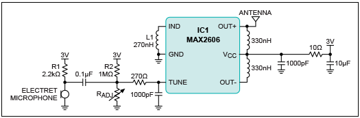 Liczba 1. Obwód FM nadajnika z mikrofonem do użytku jako telefon komórkowy umożliwiający pracę bez użycia rąk. Mikrofon bezprzewodowy 696 mW -10 dBm. PDF 3296 POBIERZ (196 KB) PDF 3006 POBIERZ (182 KB) Dławik 0,33uHz (Microhertz) = 3,3mHz (Milihertz), 0,27uHz (Microhertz) = 2,7mHz (Milihertz). |
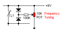
| Induktor L1 ustala Vco center szereg nastrajania. Wybierzcie L1 takie, że efektywny induktywizm od szpilki Ind do GND przyprowadza output częstotliwość 100mhz.Ta częstotliwość koresponduje z centrum grupy FM. Induktor znaczenie 270nh pokrywa nastrajanie 97mhz do 128mhz szeregu. Potem, regulujcie rezystor Radjo dla nastrajania Vco do specyficznej częstotliwości stacji FM. Rezystory R2 i Radj skłaniają wewnętrzny varactor. Stacje FM znajdują się na przedziałach 0.2 MHz przerwy. |
Liczba 2.
Obwód FM
nadajnika z bezpośrednim wkładem audio eliminuje szum tła z
mikrofonu
.Transmitter CD 696 mW -10 dBm POBIERZ PDF MAX2605-2609 (318 KB) |
|
VCO potrafi ze zróżnicowanej mocy wyjściowej z do -8 dBm. Na mikrofon elektretowy wpływają z R1. AC-łączyć/połączyć mikrofon sygnał dźwiękowy moduluje Częstotliwość VCO przez zmienianie V TUNE. częstotliwość VCO wyjściowa będzie przestrzegać pojemności albo amplituda z mikrofonu. Sygnał dźwiękowy z około 20 mV RMS jest odpowiednie dla funkcjonalność. Nie górny-modulujcie Vco, czy resulting dźwięk od odbiorcy FM będzie wykrzywione. Górny-modulując Vco również osłabia carrier sygnał, wypuszczając potęgę na niewykorzystanym spektrum odbiorcą. W Figurze 2, mikrofon i R1 zamieniają się z prostym podłączaniem dźwiękowy port wyprowadzenia komórkowego telefonu. Objętości komórkowego telefonu należy być skorygowany odpowiednio dla optymalne wykonanie. Proste podłączanie do komórkowego telefonu wyłączy tło szum mikrofon.MAX2606 45mhz do 650mhz, Zjednoczył IF Vcos z Dyferencjałem Output. KODY PASKOWE REZYSTORÓW I DŁAWIKÓW |
|
|
 |
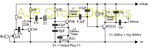
Home / Radio / DIY Crystal Oscillator Circuit crystal
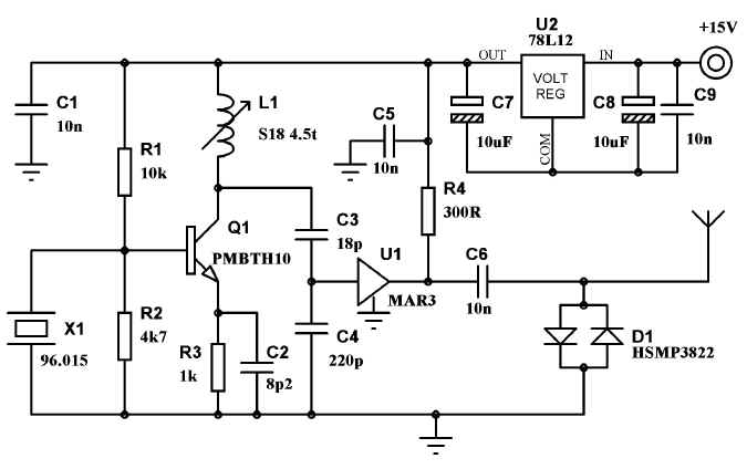
quartz oscillator circuit diagram A very simple DIY crystal oscillator circuit which use a quartz for frequency stability and a good rf transistor. Use a 2-nd or 3-rd harmonic crystal, for example if you want 100MHz use a 50MHz or 33.3 MHz quartz or if you want use a 4-th harmonic crystal but the output rf voltage will be lower. The L coil has 5 turns 0.8mm Ø, 6mm Ø, 1 mm step, output at first turn from voltage plus. Use C4 for fine frequency adjustments. For a great frequency stability, this crystal oscillator circuit must use a good varicap diode (you can use BB139) and a good crystal too. Related Products: Oscillators and Crystals | Crystals | SMD Crystal Oscillator | TH Crystal Oscillator DIY crystal oscillator circuit components
|
|
|
 |
 |
|
|
|
|
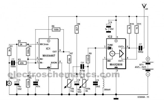
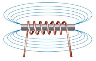
Ten prosty FM mikrofon bezprzewodowy nadajnika może transmitować mowę nad krótki zasięg. Można go używać jako prosty cordless mikrofon. Obwód używa dwóch integrujących - obwodów od maxim. IC1 MAX4467, są amplifikatorem podnoszą sygnał mikrofonu poziom stosowny dla częstotliwości modulacji. IC2 są kontrolującym oscylatorem z zintegrowanym varactor (a.k.a varicap dioda). On jest taki mały że może znaleść zastosowanie w bezprzewodowym mikrofonie reporterskim. Bezprzewodowy mikrofon zapewnia oscylację częstotliwości około 100 MHz. Dla niego najlepszy sygnał, L1 musi być wysokości składnikiem. nominalna częstotliwość oscylacja ustawia induktor l1. Ten induktor ma wartość 390 nH L1 może składać się 4 zwoji o średnicy 10 mm. Cewkę rozciągnoć na długość około 1,5 cm. |
|
Średnica drutu może
być czymś między 26 SWG (0.5 mm) i 20 SWG (1 mm). Żaden rdzeń nie
jest używany. |
|
|
|
|
|
|

|
|
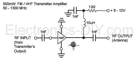
Ten nadajnik FM UKF będzie wyjście około 250mW mocy
RF za pomocą tranzystora wyjściowego 2N3866 i może pracować między
75MHz i 146MHz . narzędzia on zmienny o wysokim wzmocnieniu dźwięku
przedwzmacniacza , który może wykryć głosy 40 stóp od korzystania z
mikrofonu elektretowego . Za pomocą skanera NBFM, przebiega 5KM
zostały osiągnięte
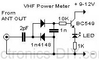
4 obroty na 85MHz do 100MHz i 3 włącza do 100 do 146MHz . Dla częstotliwości powyżej 100 MHz Crystal będzie większe niż 20 MHz tym samym podstawa emiter kondensator powinna być 47pF . L3 jest dławik 4.7uH . Jest to idealne miejsce , aby dostroić się tym obiegu za pomocą miernika fali detektora umieszczone kilka cali od nadajnika. |
Transmitter 250 mW stabilizowany rezonatorem kwarcowym. Sprawdzony zasięg w terenie zabudowanym (pomieszczenie ekranowane) antena 10cm, zasięg bez szumów 25 metrów. Dławik 4700nh. PDF BC547 POBIERZ (191 KB) PDF CERAMIC TRIMMER POBIERZ (633 KB) |
|
|
 Transmitter 88-104 Mhz. Zasięg 20 - 50 metrów. Fm. PDF BC547 POBIERZ (191 KB) PDF 2N2222 POBIERZ (107 KB) |
Wzmacniacz wysokiej czenstotliwości - 0,6W. |
|
|
|
22SWG = Średnica w mm : mm 0.711 mm Średnica w calach : w 0.028 in Powierzchnia przekroju w milimetrach kwadratowych : 0.3973 mm2 |
|
|
|
|
|
 Inteligentny przedwzmacniacz PDF AVT 2312 POBIERZ (1,07 MB) |
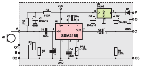
Opisany dalej układ doskonale współ−pracuje z mikrofonem elektretowym, ale bez przeróbek może też współpracować z innymi źródłami sygnału. Może więc pełnić funkcję uniwersalnego niskoszumnego przedwzmacniacza mikrofonowego z auto−matyką. W tej roli znajdzie zastosowanie we wszelkich systemach nagłośnienia, w układach telekomunikacyjnych i radioko−munikacyjnych, telekonferencyjnych, w dy−skotekach, systemach rozgłaszania (np. dworce PKP i PKS), itp. Będzie też znako−mitą pomocą przy wszelkich nagraniach, pełniąc rolę skutecznego ogranicznika, nie dopuszczającego do przesterowania toru zapisu. Szczególne właściwości układu u−możliwiają wykorzystanie go jako gitarowe−go efektu wybrzmiewania (sustain) o bar−dzo dobrej jakości. |
|
|
|
Specyfikacja Moc: Prosty nadajnik radiowy 400 mW.
Zasilanie nadajnika: 12-14 V Częstotliwość pracy: 87,5-108 MHz
stabilizowany. Pobór prądu: 100 mA. RF moc: 400 mW. Impedancja:
50-75 ohm. Modulacja: FM szerokopasmowa.
Czytaj dalej... L1 30nH (0,03uH) L2 60nH (0,06uH) L3 30nH (0,03uH) POBIERZ PDF BFR96 (117 KB) POBIERZ PDF BB112 (74,7 KB) POBIERZ PDF BB409 (59,5 KB) POBIERZ PDF BB105 (1,24 MB) POBIERZ PDF BB204 (33,9 KB) PDF BB145 POBIERZ (140 KB) PDF 3296 POBIERZ (196 KB) PDF 3006 POBIERZ (182 KB) PDF CERAMIC TRIMMER POBIERZ (633 KB) PDF BB105B POBIERZ (178 KB) PDF BFR91A POBIERZ (139 KB) |
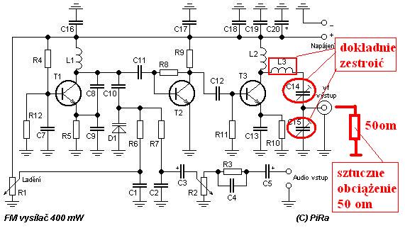 Vf výkon: 400 mW. Frekvence: 87,5-108 MHz. Modulace: FM širokopásmová. |
|
|
 Miniaturowy wzmacniacz stereo z układem TDA2822M PDF TDA2822M POBIERZ (74,4 KB) |
Miniaturowy wzmacniacz stereo z układem TDA2822M DUAL LOW VOLTAGE POWER AMPLIFIER DESCRIPTION The UTC TDA2822M is a monolithic integrated audio amplifier in a 8-Pin plastic dual in line package. It is designed for portable cassette players and radios. FEATURES *Wide operating supply voltage:Vcc=1.8V- 12V. *Low crossover distortion. *Low quiescent circuit current. *Bridge/stereo configuration. |
|
|
|
Miniaturowy wzmacniacz mono z układem TDA2822M Wzmacniacz charakteryzuje się minimalną ilością elementów zewnętrzych. Nie wymaga żadnego strojenia ani regulacji. Pracuje od razu po prawidłowym zmontowaniu. Może mieć zastosowanie jako dodatkowy wzmacniacz do walkmana, do samodzielnie konstruowanych odbiorników radiowych, pozytywek. Ze względu na niewielkie wymiary płytki może być również zastosowany w miejse trudno dostępnych układów w sprzęcie RTV. Niewielki pobór prądu umożliwia zasilanie układu z baterii. |
 Miniaturowy wzmacniacz mono z układem TDA2822M PDF J-245 POBIERZ (1,10 MB) |
|
|
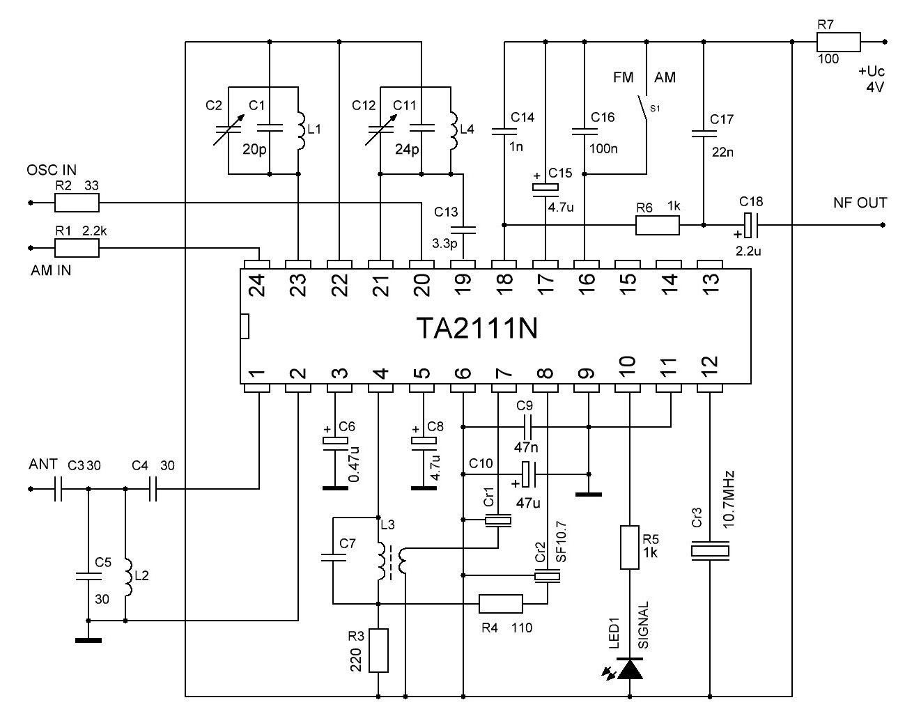 PDF TA2111N POBIERZ (597 KB) |
Радиоприемници, базирани върху шаси от "Геолог" Част IV: FM/AM приемник с ИС TA2111N Интегралната схема на TOSHIBA TA2111N е изключително подходяща за изработване на радиоприемници със задоволително качество и малък брой елементи, което е моята цел в тази серия от конструктивни решения. Естествено има и други такива интегрални схеми като TA8164P, TA8132 и т.н. Трябва да подчертая, че със сигурност разработените радиоприемници са далеч с по-добри характеристики от оригиналния радиоприемник, дори само с факта, че добавяме съвременен УКВ обхват 87-108 MHz. Интегралната схема TA2111N позволява цялостно решение на радиоприемник за АМ и УКВ. В моите схеми стереодекодера е изключен, тъй като шасито на ГЕОЛОГ не позволява тази хубава възможност. Но тъй като аз публикувам оригиналите на печатните платки, естествено всеки може да си ги модифицира и да го добави. Czytaj dalej... |
|
|
|
long range fm transmitter This is very stable, harmonic free, long range fm transmitter circuit which can be used for fm frequencies between 88 and 108 MHz. This can cover 5km range (long distance). It has a very stable oscillator because you use LM7809 stabilizer which is a 9V stabilized power supply for T1 transistor and for frequency adjustment that can be achieved by using the 10K linear potentiometer. The output power of this long range rf transmitter is around 1W but can be higher if you use transistors like KT920A, BLX65, BLY81, 2N3553, 2SC1970, 2SC1971… Czytaj dalej... |
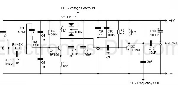
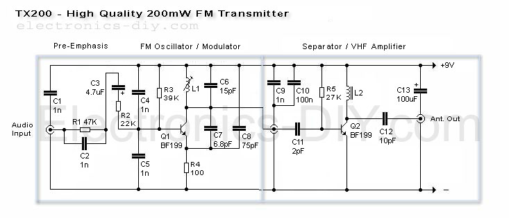
Fm transmitters PDF 199 PHILIPS POBIERZ (49,1 KB) PDF BF199 POBIERZ (144 KB) PDF 3296 POBIERZ (196 KB) PDF 3006 POBIERZ (182 KB) PDF CERAMIC TRIMMER POBIERZ (633 KB) |
|
|
|
fm transmitter circuit schematic PDF BF982 POBIERZ (128 KB) |
The most important part of this 88-108 transmitter is
the Colpitts oscillator. C3,C4,C5,C6,CD1-CD2 ans L1 determine the
transmission frequency. The RF Oscillator
circuit has the BF982 MosFet transistor wich is the active part. The
others 2 transistors separate the VCO from antenna. FM transmitter circuit diagram The first stage BF199 amplifies the weak signal from the vco and functions in constant load. The second stage BFR90 amplifies the rf signal to load the antenna wich will radiate the radio frequency power. Antenna can be one wire, 70 cm long. L1 coil has 1mm thick copper wire, 3.5 turns, 5 mm diameter and 1mm space between turns. You can use BF199 instead of BFR90 and MV104 instead of the 2 varicape diodes. Czytaj dalej... |
|
|
|
Pira CZ 5W PLL FM Transmitter Easy to build high-quality PLL FM transmitter with typical output power of 5 W and no-tune design. The transmitter includes RDS/SCA input and Audio/MPX input with optional preemphasis. It can be used with or without stereo encoder. Tuning over the FM band is provided by two buttons that control dual-speed PLL. The transmitter can work also without the LCD display. Some experience with building devices of this kind are highly recommended. Characteristics Supply voltage 11-13.8 V (stabilised or from a battery) Supply current up to 1.2 A Standard frequency range 87.5-107.9 MHz Audio/MPX input sensitivity 2 V pp (for 75 kHz freq. deviation) RDS/SCA input sensitivity 0.2 V pp (for 7.5 kHz freq. deviation) Board dimensions 109 x 54 mm Czytaj dalej... |
 Transmitter 5W |
|
|
 PDF 3296 POBIERZ (196 KB) PDF 3006 POBIERZ (182 KB) PDF CERAMIC TRIMMER POBIERZ (633 KB) |
Transmitter w.cz 87-107 MHz Then you can connect antenna and audio signal. Adjust R1 until the audio sounds as loud as the other stations, With a good antenna (dipole placed outdoor and high) the transmitter has very good coverage range about 1500 meters, the maximal coverage range is up to 20 km. |
|
|
|
Schemat generatora z separatorami. |
 Płytka drukowana GIF (6,21 KB) PDF 3296 POBIERZ (196 KB) PDF 3006 POBIERZ (182 KB) |
|
|
 PDF CERAMIC TRIMMER POBIERZ (633 KB) |
Schemat stopni mocy nadajnika fm. |
|
|
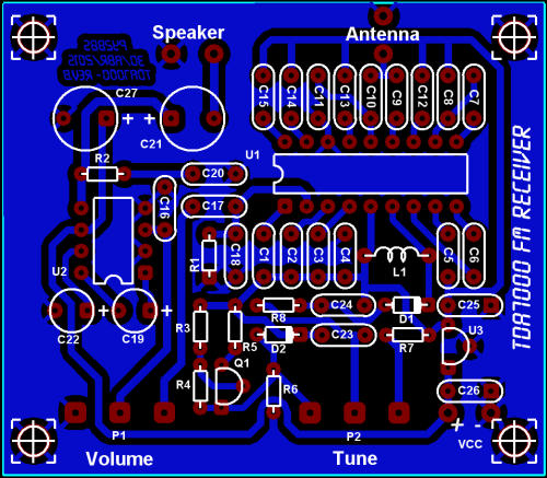
| Transmitter FM. Wykaz elementów PNG (38,6 KB) |
PDF CERAMIC TRIMMER POBIERZ (633 KB) |
|
|
|
|
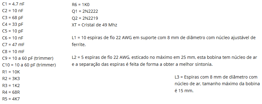
Transmitter stabilizowany rezonatorem kwarcowym 49 MHz. Wykaz elementów PNG (27,8 KB)
|
|
|
|
|
|
|
 |
|
|
|
|
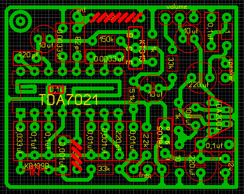
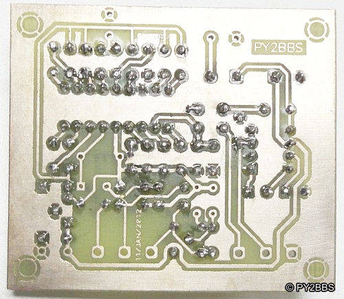
Odbiornik radiowy UKF na pasmo 66-110Mhz Odbiornik przeznaczony jest do odbioru audycji nadawanych w paśmie 88-108 Mhz. Zbudowany jest na układzie TDA7020 (TDA7021). Układ ten zawiera w swojej strukturze wszystkie tory odbiornika FM: wzmacniacz w.cz., heterodynę, mieszacz, wzmacniacz p.cz, demodulator i układ wyciszania. Odbiornik ten cechuje brak elementów indukcyjnych w torze p.cz., co osiągnięto dzięki zmniejszeniu częstotliwości pośredniej do 76kHz. Podstawowe parametry układu TDA7020: - napięcie zasilania 1,8-V - stosunek sygnału do szumu 60dB - prąd zasilania 6mA - czułość przy S/N -26dB - zakres ARCz 160kHz L1 najwygodniej nawinąć na wiertle o średnicy 5 mm. Należy nawinąć 5 zwojów drutu o grubości 0,7 mm. (20nH) Cewkę L2 obwodu heterodyny nawinięto na korpusie z filtru 7 x 7. Uzwojenie ma 4 zwoje drutu CuAg fi 0,8. (36nH) |
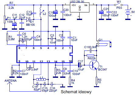 TDA7020 MC1309P STEREO PDF 3296 POBIERZ (196 KB) POBIERZ PDF BB105 (1,24 MB) PDF J081 POBIERZ (291 KB) PDF 78L05ACZ POBIERZ (66,8 KB) PDF 78L05 POBIERZ (980 KB) PDF TDA7021 POBIERZ (145 KB) PDF TDA7021T POBIERZ (145 KB) |
|
|
|
|
|
|
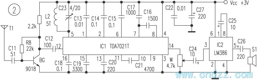
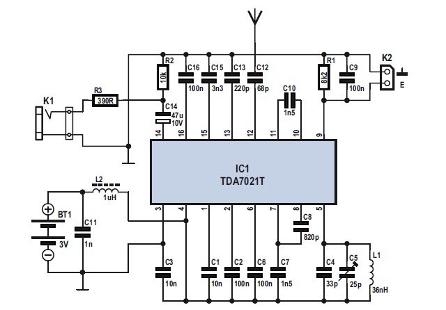 Odbiornik FM TDA7021T PDF TDA2021T (145KB) Dławik 1uHz = 1000nHz |
 Odbiornik FM 88-110Mhz PDF TDA7000 (224KB) PDF SCHEMAT (3,19MB) |
|
|
 Odbiornik FM 88-110Mhz PDF AVT495 (176 KB) |
 FM Receiver TDA7000 PDF TDA7000 (224KB) PDF TBA820M (95,4 KB) PDF BB204 (33,9 KB) |
|
|
|
|
 |
||
|
|
|
|
60-120MHz FM Receiver with AFC March 20, 2015 / by circuit wiring / in RF Radio Circuits We can say in simple words that AFC will lock the receiver to any valid RF signal. Below, we can see a basic block diagram of an receiver. The VCO is mixed with the RF signal which enter the mixer (yellow). The VCO can be a coil and a tunable capacitor. To bring out the sound from the FM signal, the product from the mixer is filtered and enter the demodulator (blue). 60 120MHz FM Receiver with AFC Now you feel the different in tuning with or without AFC. You have to ve very steady on your hand without AFC and if you touch any component the frequency will change. When you are trying to find narrow band signals, this is specially annoying. Just let the tunable capacitor slide and my receiver locked to all kinds of signals when the AFC is connected. The receiver could even locked the police frequency which is narrow band FM signal (5kHz). |
 |
|
|
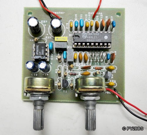
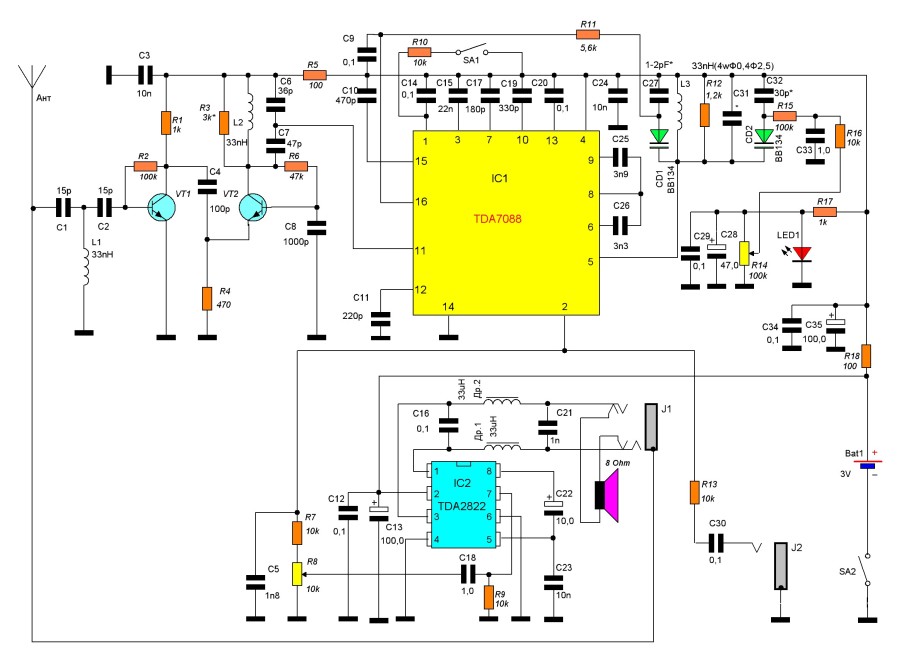
 PDF ODBIORNIK UKF FM TDA7088 POBIERZ (1,30 MB) |
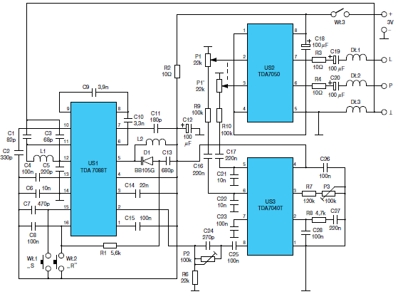
Kieszonkowy odbiornik stereofoniczny UKF FM Do budowy odbiornika wykorzystano nowoczesne układy scalone firmy Philips. Zasadnicza część odbiorcza wykorzystuje układ TDA 7088T. Jest to układ w obudowie typu SO16 przewidzianej do montażu powierzchniowego. Zawiera w swoim wnętrzu: pełny tor odbiorczy FM mono z demodulatorem, obwód wyciszania, układ automatycznego przestrajania wspópracujący z zewnętrzną diodą pojemnociową, zabezpieczenie przed odwrotną polaryzacją zasilania. Minimalne napięcie zasilania wynosi 1,8 V co pozwala na zasilanie napięciem 3 V (dwa ogniwa R6). Maksymalne napięcie zasilania nie powinno przekroczyć 5 V. Typowy pobór prądu wynosi 5,2 mA. Zakres temperatur pracy -10÷+70° C SCHEMAT TDA7088T GIF |
|
|
|
 PDF TDA7088 POBIERZ (252 KB) |
|
|
 |
Радиоприемникът в оригиналното си изпълнение беше с автоматична настройка на станциите с един бутон и допълнителен бутон за начално установяване на честотата. При стационарна работа беше много неудобно търсенето на любимите радиостанции отначало при всяко изгасяне и запускане. След като премахнах резистор в автоматиката, управляваща с напрежение варикапа за настройка, чрез 10 оборотен потенциометър радиоприемникът вече се настройва ръчно. Напрежението за настройка варира от 1,2 до 3V, при което приемания УКВ обхват е от 87,6 до 108 MHz. След това премахнах ненужните електронни елементи като светодиод, транзистор за усилвател на слушалките и превключвател с две положения за гръмкостта. SCHEMAT CD9088 LM386 GIF |
|
|
|
За бъдещи приложения бих използвал LM386 като нискочестотен усилвател, свързана по следната принципна електрическа схема: Експерименталната платка "с квадратчета" на показания усилвател се "подхвърля" два-три дни, при което я свързвах към късовълновото радио, компютър, mp3 плеър и др. звукови източници. За SMD корпус с размери 4мм х 4мм х 1мм интегралната схема се справяше добре - изходящата мощност е достатъчна за озвучаване на стая, с поносимо качество. |
 |
|
|
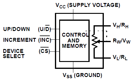
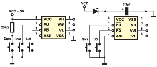 Potencjometr cyfrowy 100 k ohm PDF X9C104 POBIERZ (231 KB) PDF XICOR POBIERZ (488 KB) |
Xicor wyprodukował pierwsze potencjo− metry EEPOT w roku 1987 w technologii NMOS. Choć te pierwsze wyroby charaktery− zowały się dużym poborem energii, znalazły szereg zastosowań i przyjęły się na rynku. W roku 1992 wprowadzono drugą generację potencjometrów elektronicznych, wykona− nych w technologii CMOS, co było niewątpli− wym przełomem ze względu na zmniejszenie poboru prądu. W roku 1995 pojawiły się ukła− dy o niskim napięciu zasilania (3V). Dalszym krokiem było pojawienie się układów trzeciej generacji, charakteryzujących się mniejszymi szumami i jeszcze mniejszym poborem mocy. |
| Potencjometry firmy Xicor oznaczane są przez producenta skrótem XDCP − Xicor Digitally Controlled Potentiometer. Od dawna docenianą zaletą układów firmy Xicor jest obecność nieulotnej pamięci EEPROM, dzięki której nastawy potencjometrów są zachowywane po wyłączeniu i włączeniu zasilania. Dlatego potencjometry te oznaczane są także EEPOT lub E2POT. Potencjometr cyfrowy jest w rzeczywistości zespołem wielu (np. 100) rezystorów i przełączników CMOS. Logiczne układy sterujące włączają odpowiednie klucze odpowiednio do zawartości licznika. W praktyce w strukturze zawarte jest od 16 do 256 przełączników, a rezystorów zawsze o jeden mniej. Jeśli wszystkie rezystory składowe są jednakowe, uzyskuje się potencjometr o charakterystyce liniowej. |
 X9C104 |
|
|
 Potencjometr cyfrowy - audio PDF DS1669 POBIERZ (173 KB) |
FEATURES Replaces mechanical variable resistors Electronic interface provided for digital as well as manual control Wide differential input voltage range between 4.5 and 8V Wiper position is maintained in the absence of power Low-cost alternative to mechanical controls Applications include volume, tone, contrast, brightness, and dimmer control Available in 8-pin SOIC and 8-pin DIP packages Standard resistance values for Dallastat: DS1669-10 ~ 10 kΩ DS1669-50 ~ 50 kΩ DS1669-100 ~ 100 kΩ Operating Temperature Range Industrial: -40°C to +85°C |
|
|
|
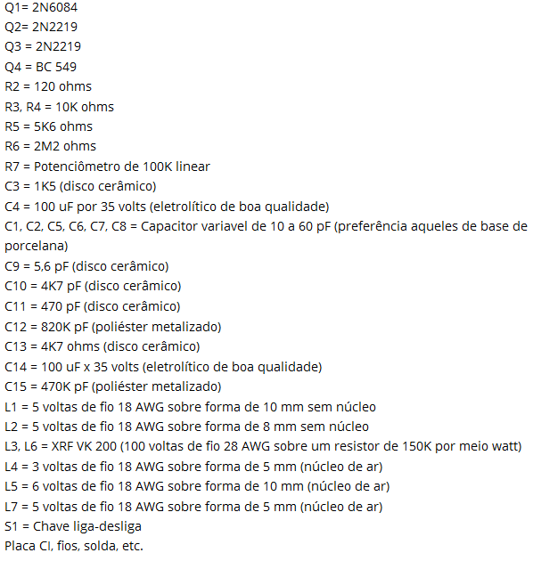
Aircraft / Airplane Radio Receiver Component List: R1, R3 - 47K 1/4W Resistor R2 - 10K 1/4W Resistor R4 - 4.7K 1/4W Resistor R5 - 5K Linear Taper Pot R6 - 2.2K 1/4W Resistor C1, C2, C3, C6 - 0.001uF Ceramic Disc Capacitor C4 - 2.2pF Ceramic Disc Capacitor C5 - 1pF Ceramic Disc Capacitor C7 - 15uF 15V Electrolytic Capacitor C8 - 18pF Variable Capacitor D1 - 1N82 Diode Q1 - 2N918 NPN Transistor L1 - See Notes L2 - 1.8uH Inductor ANT1 - Approx. 18 Inch Wire Antenna MISC - PC Board, Wire, Knob For C8 |
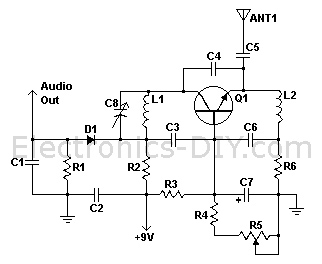
Voltage Supply: 9-12V Aircraft / Airplane Radio Receiver Operating Frequency: 220MHz - 400MHz Czytaj dalej... |
|
|
 |
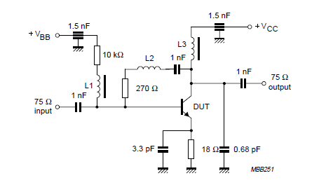
High Frequency VCO Design and Schematics
Czytaj dalej... PDF SMV1232 POBIERZ (972 KB) PDF 3296 POBIERZ (196 KB) PDF 3006 POBIERZ (182 KB) |
|
|
|
This simple transmitter allows you to broadcast on FM
radio band 87.5 - 108 MHz. It consists of a simple oscillator with
silicon planar RF PNP transistor. Directly to the oscillator an
antenna is connected. Due to the large amplitude of RF voltage is
sufficient antenna length of about 5-10 cm. I used insulated 7cm
long copper wire 1mm diameter. I eliminated the tuning capacitor,
which is usual for most bugs and miniature transmitters, because
this greatly complicates the tuning. From my own experience I know
that if you get closer to such capacitor, the operating frequency is
changed. That's why I chose to use the voltage tuning using the
Voltage Controlled Oscillator (VCO). Instead of tuning capacitor the
varicap (capacitance diode) is used, which changes its capacity by
changing the reverse DC voltage. We can tune the operating frequency
by changing the DC voltage using the trimmer P1. Varicap also
provides frequency modulation. Inductor L1 is
airborne and has six turns of 0.5 mm diameter wire wound on 3 mm
diameter. Inductor L1 with turns close together - larger inductance
- lower frequency. L1 with outstretched turns - lower inductance -
higher frequency.
Czytaj
dalej... |
Single Transistor VCO FM Transmitter PDF BBMV2101 POBIERZ (69,7 KB) PDF BBMV209 POBIERZ (63 KB) PDF BF970 POBIERZ (74,1 KB) PDF BF979 POBIERZ (71 KB) PDF BC559 POBIERZ (89,4 KB) PDF 3296 POBIERZ (196 KB) PDF 3006 POBIERZ (182 KB) |
|
|
 |
This simple homemade television transmitter allows you to broadcast TV picture on the UHF band 470-855 MHz. The frequency is determined by the values of components L1 and C1. The values given in the schematic diagram set the transmitter to about 600-700 MHz, that is in the range of 37. - 50. channel of analogue TV bands. The television transmitter consists of a simple oscillator with high frequency NPN transistor. Suitable are for example BFR90, BFR91A, BFR92 or BFR93. I used BFR91A in the planar to50 case. Its transition frequency is 6GHz. Carrier frequency is amplitude-modulated by the input video signal. As the video source you can use a security TV camera or camera with video output. Antenna is about 5cm (2'') of wire and is connected directly to the oscillator. The transmitted signal can be tuned on any analog TV with UHF band. Operating frequency can affect by changing values of L1 and C1. Fine tuning is possible by stretching or shrinking turns of L1. Czytaj dalej... |
|
|
|
|
1 Watt FM Transmitter Amplifier |
|
|
|
15W Transmitter Power Amplifier 88-108MHz The power amplifier boosts 88-108MHZ 1-2W FM transmitter's power to 15 W. It includes multi-level low pass filter and has a high conversion efficiency with strong Yi-wave suppression. With good antena expected transmission coverage is at least 15Km. It uses high power 175 MHZ 4A 25W 2SC1972 RF transistor that must to be mounted to heatsink for proper heat dissipation. Czytaj dalej... |
PDF CERAMIC TRIMMER POBIERZ (633 KB) |
|
|
|
|
|
|
|
|
BFR93A NPN 6 GHz wideband transistor L1 = L3 = 5uH choke. L2 - 3 turns 0,4 mm copper wire; winding pitch 1 mm; intemal diameter 3 mm. |
 PDF BFR93A POBIERZ (121 KB) |
|
|
|
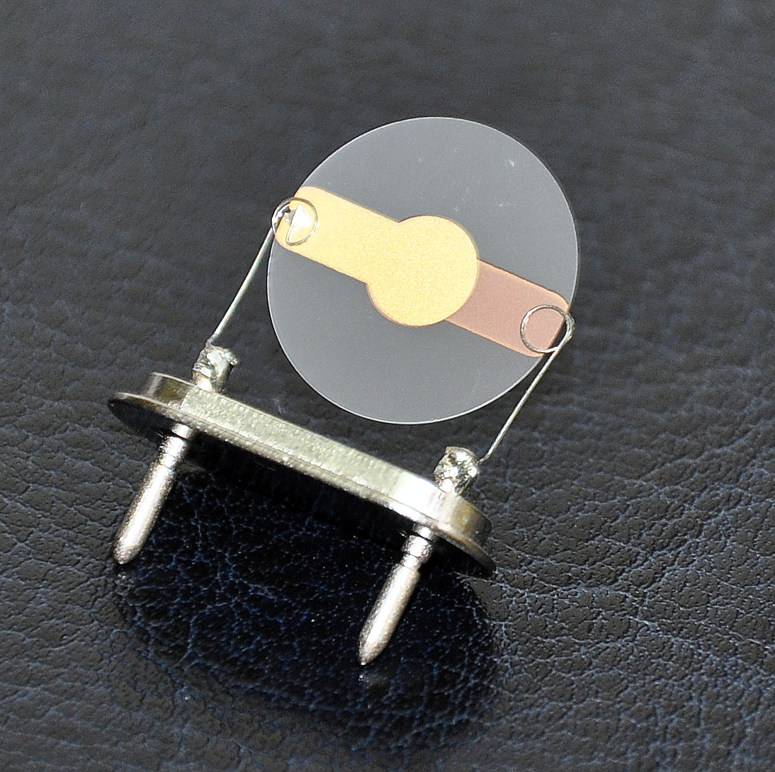
This is simple FM transmitter for FM broadcast band
in 88-108 MHz. BC 549 is small signal transistor for wide
applications, but usually for AF. You can build simple FM
transmitter with one BC549 transistor and several other component
parts. Simple FM transmitter with only one transistor is often
called bug. This project is suitable for beginners in radio amateur,
education, or hobbies. As an antenna you can connect 150cm of copper
wire. The input can be replaced with any sound source, like ipod, Mp4 player, laptop, or TV. Transistor circuit outputs 1-5 mW RF signal that can travel around 30 meters, due to limited power supply voltage, limited modulation, very loose coupling with the Antenna. The Antenna has to be connected either directly to the tank circuit or via a small capacitor. The Antenna now forms part of the tuning circuit. If you approach the antenna, the frequency of the oscillator may shift slightly. This effect is called Frequency Pulling. The frequency of operation shifts as the battery runs down. This effect is called Frequency Pushing. The internal capacitance of the transistor also changes with the temperature of the transistor. The tuning capacitor also changes values slightly with temperature. So one experiences a slow frequency drift till the transmitter reaches thermal equilibrium with its surroundings. |
Simple FM Transmitter with BC549 |
|
|
 PDF CERAMIC TRIMMER POBIERZ (633 KB) |
|
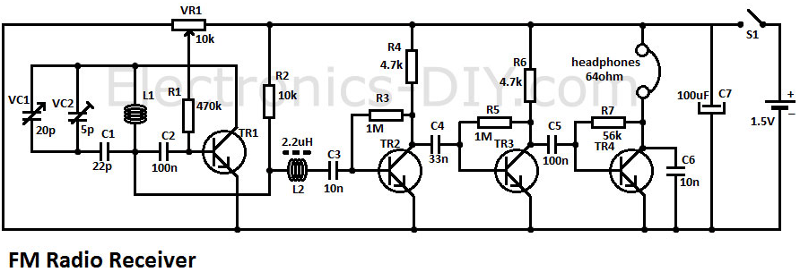
This FM radio receiver circuit is very simple to
build and is powered by just a single 1.5V battery cell. Receiver
consists of a regenerative rf stage, TR1, followed by a two of
three-stage audio amplifier, TR2 to TR4. In some areas 3 stages of
audio amplification may not be necessary, in which case TR3 and its
associated components can be omitted and the free end of capacitor
C5 connected to the collector of TR2. The critical part of the fm
radio receiver is the first stage, TR1/VC1, where the wirings must
be kept as short as possible. Coil L1 is formed by winding 8 turns
of 1mm (20 swg) enamelled copper wire on a 6 mm diameter former,
which is then removed. After that L1 should be stretched carefully
and evenly to a length of about 13mm. The tunning capacitor VC1 is one of the two fm sections of a miniature fm transistor radio with built-in trimmers (VC2). The earthy end (moving vanes and spindle) is connected to the 22pF capacitor C1. The value of the rf choke L2 is not critical, anything from 1ľH to 10ľH being suitable. The output is suitable for ordinary earphones connected in series to provide an impedance of 64Ω. Tuning-in the fm radio receiver To operate the receiver, potentiometer VR1 must first be advanced slowly (towards the end of the track connected to battery positive) until, at about the half-way point, a sudden slight increase in background noise will be heard, indicating the onset of oscillation. It then should be backed off, very slowly, until oscillation just stops; it then should be possible to tune in some stations. The correct frequency range of 87 MHz to 108 MHz can be obtained by adjusting VC2 at the high frequency (108 MHz) and slightly stretching or squeezing together the turns of coil L1 at the end (87 MHz). FM Radio Circuit Diagram fm radio receiver circuit diagram Transistors List: TR1 = BF199 TR2 = TR3 = TR4 = BC547 |
|
|
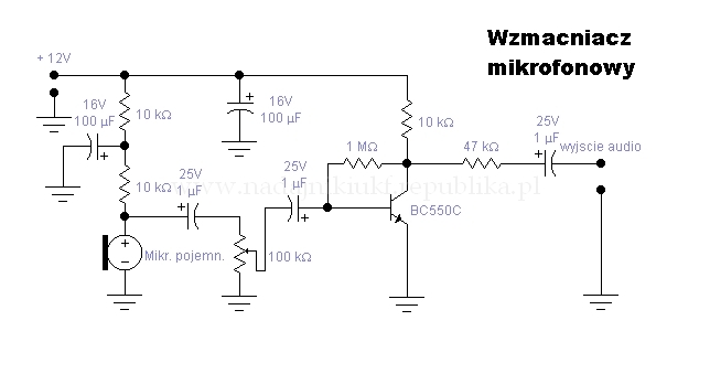 |
Simple microphone preamplifier Summary of circuit features Brief description of operation: Simple microphone preamplifier Circuit protection: No special protection circuits used Circuit complexity: Very simple one transistor circuit Circuit performance: Amplification 35 dB, flat frequency response from 20 Hz to 20 kHz, quite poor distortion performance figures, a little bit noisy Availability of components: Uses common and easily available components Design testing: I have built few microphone preamplifiers based on this circuit and theu have worked without problems. |
|
Applications: Interface dynamic or electret microphone to a line level audio input in HIFI amplifier or computer soundcard. Power supply: 9V battery, takes less than 10 mA current Estimated component cost: Electronics components than $10 Safety considerations: No special electrical safety considerations. Circuit description This is a simple microphone preamplifier circuit which you can use between your microphone and stereo amplifier. This circuit amplifier microphone suitable for use with normal home stereo amplifier line/CD/aux/tape inputs. This microphone preamplifier can take both dynamic and electret microphone inputs (preamplifier provides power foe electret microphone elements). The idea of this circuit is to keep the design as simple as possible to be easy to build. That was my goal when I needed a simple external microphone preamplifier for my mixer. The performance of the circuit is nothing superior but can be used with many not so serious projects. The circuit is a simple one transistor amplifier with amplification of about 30-40 dB (depends on transitor, temperature and voltage). |
| The dynamic mic input is just a simple one transistor amplifier circuit with nothing special in it. LED D1 is in the circuit to show that the circuit operates. The voltage drop caused by LED (around 1.8V for RED led) has been taten in account when designing the amplifier circuit built around Q1. Resistor R4 and capacitor C5 make a filter to filter out possible noise from battery or other power source which is used to feed this circuit. Capacitors C1, C2 and C3 are used to block the DC bias on Q1 base to flow out of microphone input to microphone (the polarity of all capactors is straigh line = + and curved line = -). |
 |
|
Electret microphone input has a resistor R1 fo feeding current through electret microphone capsule when it is connected to the electret microphone input. Electret microphone needs some current (about 1 mA) flowing through it to operate, because there is a small amplifier circuit inside the microphone capsule. This circuit is suitable for all typical cheap electret capsules which available from any electronic component shop. Because electret microphones have higher signal level output, it is quite easy to overdrive the amplifier when you shout to electret microphone. The circuit is bet to build to a small metal box like in the picture above. Put the 9V battery inside the case too. Battery power and metal box keep external noise and interference sources away. I used standard 6.3 mm jack for dynamic microphone and 3.5 mm mono jack for electret micrphone both installed to from, panel of the metal box. The LED and power switches are also installed to front panel. Measured specifications from protype Frequency response: 20 Hz to 20 kHz +-1dB Noise level (A-weighted): -85 dBm Amplification: 35 dB Because of the simplicity of the design the distortion performance is not very good. |
|
|
At signal levels typically used by electret microphones the distortion is about 2-3%. With dynamic microphones the distortion level is lower (not measured). Here is the frequency response as measured by LoudSpeaker LAB software DEMO version with Sound Blaster 16 PNP card: The bass frequency attenuation is caused by the microphone preamplifier circuit. The high end attenuation is caused by Sound Blaster 16 card. As seen in the measured performance, the microphone preamplifier is suitable for speaker measurements made using suitable measurement software and sound card. Using this preamplifier connected to line level input the problems caused by poor microphone preamplifier in many sound cards can be avoided. Component list R1 4.7 kohm R2 220 kohm R3 2.2 kohm R4 120 ohm C1..C4 10 uF 16V electrolytic C5 100 uF 16V electrolytic D1 Red LED Q1 BC547B SW1 on/off switch If you can't find all the components on the shop near you take a look at component replacement tips. |
|
If you happen to have hard time finding BC547 transistor, you can use 2N2222 transistor instead. The circuit has been reported to work well with it also (although there might be some slight performance changes though, I have not tested and mearured the circuit with 2N2222). Modification ideas If you plan to use this circuit with a soundcard electret microphone which has 3.5 mm stereo plug, then you have modify the circuit to make it work work this type of multimedia microphone. You don't have to make many changes: just replace the 3.5 mm mono jack with stereo jack. In the original circuit R1 goes to the tip of the microphone connector, but now you connect R1 to go to the ring of the connector. If you want an adjustable output signal level for the microphone preamplifier you can add this quit easily by connecting one 10 kohm logarithmic potentiometer to the circuit output in the following way: |
|
|
|
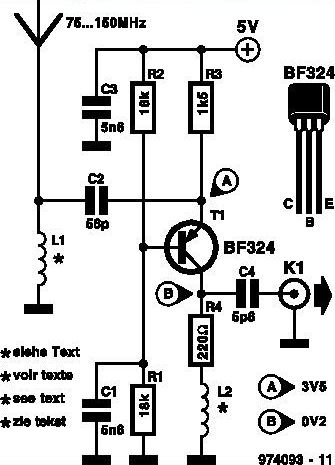
This inexpensive FM radio receiver antenna booster uses the BF324 TO92 style pnp transistor in a grounded-base configuration. The circuit may be used as a signal booster with VHF receivers whose front end suffers from low sensitivity (such as many valved and army surplus types). The frequency range of the preamplifier is roughly from 75MHz to 150MHz. The two inductors in the circuit are home made. L1 consists of 10turns of 24SWG enamelled copper wire; the internal diameter is 3mm, no core. Inductor L2 has 13 turns of the same wire, and an internal diameter of 5mm; no core is used either. A construction tip: close-wind the inductors using 3 and 5mm drill bits respectively as temporary formers. The prototype of the preamplifier was successfully used with an 88-108 MHz FM broadcast receiver and a 2-metre VHF ham receiver. The preamplifier draws about 2.5mA from a 5-volt supply. Wideband FM antenna booster circuit schematic |
 |
|
|
|
|
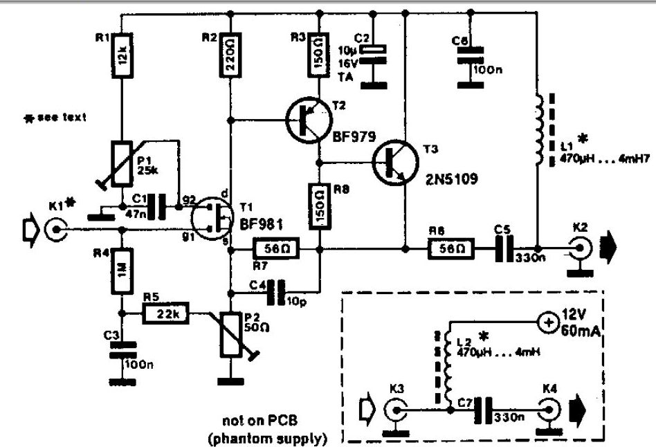
Wideband Active Antenna Circuit |
|
|
|
UHF Antenna Amplifier Circuit This amplifier circuit is used to amplify TV signals in UHF range. It uses a low-noise transistor and gives 10 to 15 dB amplification in the frequency range from 400 MHz to 850 MHz. The transistor must be shielded from the input components and in constructing this circuit, the wirings must be as short as possible. For best results, the cable must be directly soldered to the PCB. The circuit should be installed near the antenna and housed in a water proofed case. The power supply for this uhf tv antenna amplifier is fed through the cable by using a choke coil. To prevent the DC voltage from getting into the TV set, the coaxial cable must be coupled to the set through a small value capacitor. To align the amplifier, just adjust P1 until the best reception is achieved. It means a collector current between 5 and 15 mA. PCB 1 PCB 2 |
 |
|
|
|
|
|
|
 |
 |
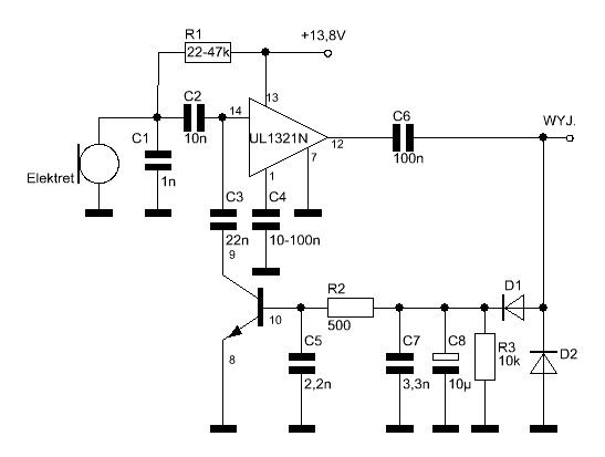 |
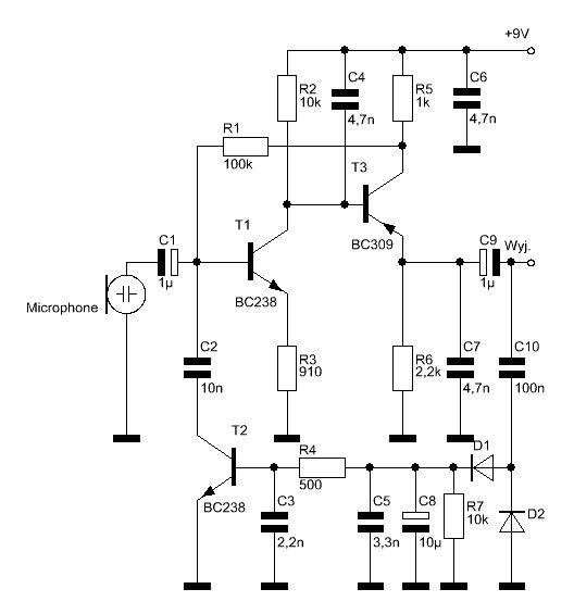
| Kompresor dynamiki 1 D1,D2 - dowolny BYP. AAP152 (germanowa), 1N4148 (przełączająca). | Kompresor dynamiki 2 | Kompresor dynamiki 3 D1,D2 - dowolny BYP. AAP152 (germanowa), 1N4148 (przełączająca). |
|
|
 |
 |
 |
| Mini Mixer - cztery kanały wejściowe (monofoniczny). |
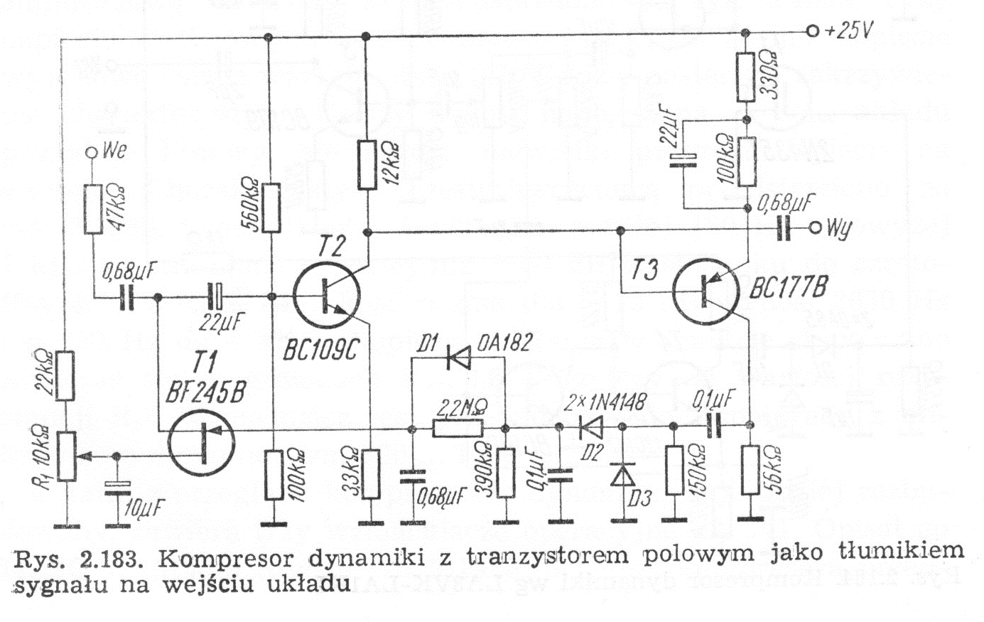
Procesor dynamiki z tranzystorem polowym jako tłumikiem sygnału na wejściu układu. |
Mikrofonowy kompresor dynamiki. |
|
|
|
|
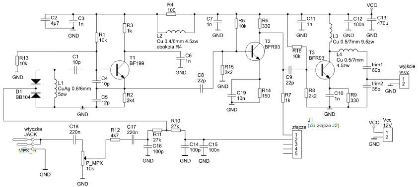
500mW PLL FM Transmitter 88-108MHz This PLL transmitter is controlled and the frequency is very stable and can be programmed digitally. Transmitter will work 88-108 MHz and output power up to 500mW. With a small change can set the frequency of 50-150 MHz. The output power is often set to several watts with transistors. So therefore I decided to build a simple transmitter with great performances. The frequency of this transmitter can easily be changed by software and space / compress air coil. This transmitter is the oscillator colpitts. Oscillator is a VCO (voltage controlled oscillator) which is set by the PLL circuit and PIC micro controller. This oscillator is called the Colpitts oscillator and voltage controlled to achieve the FM (frequency modulation) and PLL control. Czytaj dalej... |
|
|
|
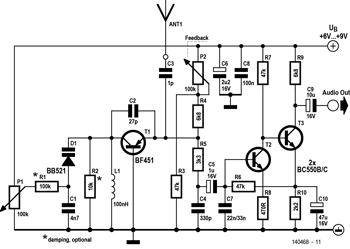
FM Synchro Receiver With capacitive three-point oscillator FM Synchro Receiver Small VHF receivers needn‘t employ complex FM demodulation circuitry nor be double superhets. Using a capacitive three-point oscillator in common-base mode as the synchro demodulator makes things a lot easier. |
 |
|
|
|
|
2N3904 |
|
|
|
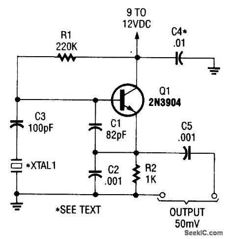
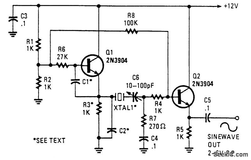
Crystal Sine Wave Oscillators |
|
|
|
|
|
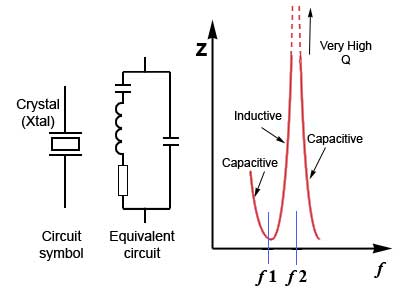
Crystal oscillators can produce
either sine wave or square wave outputs over a very wide |
|
|
|
|

|
|
|
|
|
 |
Woda (tlenek wodoru; nazwa systematyczna IUPAC:
oksydan) – związek chemiczny o wzorze H2O, występujący w warunkach
standardowych w stanie ciekłym. W stanie gazowym wodę określa się
mianem pary wodnej, a w stałym stanie skupienia – lodem. Słowo woda
jako nazwa związku chemicznego może się odnosić do każdego stanu
skupienia. Woda jest bardzo dobrym rozpuszczalnikiem dla substancji polarnych. Większość występującej na Ziemi wody jest „słona” (około 97,38%), tzn. zawiera dużo rozpuszczonych soli, głównie chlorku sodu. W naturalnej wodzie rozpuszczone są gazy atmosferyczne, z których w największym stężeniu znajduje się dwutlenek węgla. Woda naturalna w wielu przypadkach przed zastosowaniem musi zostać uzdatniona. Proces uzdatniania wody dotyczy zarówno wody pitnej, jak i przemysłowej. |
|
|
|
|
|
STRONA NR - 1 |
|
|
|
|
