|
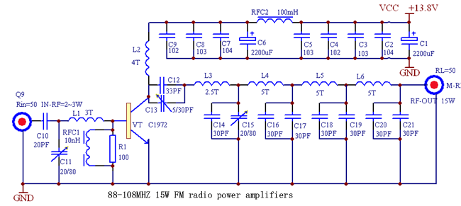
To maintain 88 ~ 108 MHZ with any
frequency output reached rating, according to the level before the
center frequency of some components to make suitable adjustments.
May, when necessary, to reduce low-ball-series, to increase power
output. The expansion of the power signals from three low-pass
filter Yi-filtered high element of the transmitting antenna feed.
Components choice: In addition to electrolytic capacitor, the other
tiles with high-frequency capacitors, C11, C12, C14 use
high-frequency characteristics of a good, stable performance of
adjustable capacitors, inductors Choke RFC1, RFC2 finished with
inductors, must pay attention to the current RFC2 Carrying capacity,
should use the coarse diameter Cores with the inductors.
L1-L6 available ř0.8mm the high-intensity enameled wire system, a
diameter of about 5 MM, a few laps in the plans to "T" for the units
indicated. Q1 ordinary Q9 socket, and supporting the use of plugs.
Q2 used for 50 Ω RF output connectors, and then of resistance is
smaller, more conducive to impedance matching. Larger effective
power more common for the launch of the C1972, of course, especially
if you sufficient money to buy blocks C2538 contour of the gain,
power will be even greater.
Debug circuit, be sure to pay attention, the power circuit, we must
connect false load (I use 30 1 W, 1500 Ω high-precision metal film
resistors made parallel), and there must be enough in the cooling
devices, normal working hours Power Of not less than 2.5 A, the
antenna impedance strictly equivalent to 50 Ω, can not be used
Duanbang drawbars antenna, or a strong current of RF feedback
circuit will create their own interference, most of RF energy to
space and can not be convergence in the consumption of power, to
overheating Damage must be launched for 50 Ω coax, tabled Reply to
launch outdoor antenna.
Circuit the normal work of the key lies in whether the circuit
debugging, the whole process had to very carefully. Debugging, enter
only the smaller the incentive power supply voltage drop to 9 V,
using high-frequency voltage (can not use ordinary multimeter)
monitoring false load at both ends of high-frequency voltage value,
regulating C12, C14, L3, L4, L5, L6 So that the voltage range of
15-20 V around, and then adjust C11, L1 voltage to the largest. And
then gradually raise the voltage, each raising a voltage repeatedly
adjusted C12, C14 and C11, L1 so that the maximum output voltage,
noted that the input voltage and RF power simultaneously increasing
incentives to ensure the accuracy of the results of debugging. Reach
rating, 13.8 V supply voltage of about 2 A current work around, 50
Ω-load resistance at both ends voltage ≥ 40 V, RF power output of 15
W.
With the RF power amplifier with 50 Ω-wide umbrella to the vertical
launch antenna (gain of about 2 dB), to ordinary FM radio test fired
from the coverage of not less than 15 KM |
